Gas Separation by Adsorption
Introduction
The Adsorption process is an important technology often applied alongside a cryogenic process to purify or dry a feed stream before it is cooled down.
Adsorption enables separation of gas species – one of which is preferentially adsorbed onto the internal surface of a porous solid ‘adsorbent’. The adsorbed species is termed the adsorbate.
This process should be distinguished from the similar word absorption where a liquid ‘solvent’ is used to remove a soluble component from a gas mixture. A common example of absorption is removal of carbon dioxide from a natural gas or a from syngas by absorption in an amine solution such as Methyl diethanolamine (MDEA).
An adsorption process is often used to purify the feed gas to a cryogenic plant such as LNG, or Air Separation in order to remove components such as water or CO2 that would otherwise freeze out and block the cryogenic heat exchangers.
Adsorption is generally a semi- batch process. It employs at least two vertical vessels packed with a ‘bed’ of adsorbent particles spheres or pellets (1-5 mm nominal diameter). The gas to be purified or separated is supplied usually at an elevated pressure and flows through one of the vessels where one component is continuously being adsorbed. This continues for a period (usually several hours) until the adsorbent ‘bed’ is nearly ‘saturated’ or loaded at which point the adsorption switches to the other vessel. The loaded vessel is then taken ‘off-line’ and its bed is regenerated – usually by a counter-current stream of heated gas. The gas flowing through the loaded bed ‘desorbs’ the adsorbate until it is fully regenerated and then re-cools it ready to be put back in service or ‘on-stream’.
Adsorbents
There are two principal types of adsorbents. Their common features are a high internal surface area and good mechanical strength. The specific adsorbent selected would be based on a high adsorbed capacity for the component to be removed.
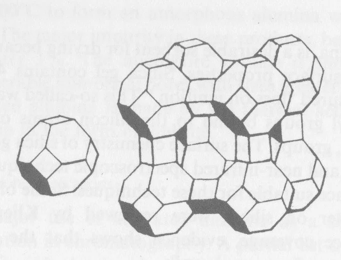
Zeolite molecular sieves type 5A (for air separation ) and 4A for LNG. The number preceding A signifies the nominal size in Angstrom units of the ‘window’ to the interior passages which provide the huge adsorption surface. Molecules larger than this window are excluded, which is the basis for the selectivity and indeed for the name ‘molecular sieve’. In addition to the naturally occurring zeolites other variations have been synthesised for specific duties including 3A, and 13X.
The picture shows Zeolite type A molecular sieve adsorbent crystal structure.
The second type of adsorbent is activated carbon which can be derived from natural carbonaceous sources such as anthracite, coconut shells or manufactured and activated at high temperature to increase the internal adsorption area.
The zeolites are most effective in adsorbing polar compounds such as H2O, CO2, H2S, NH3. The process is termed chemisorption as there is a weak chemical bond between adsorbate and adsorbent.
In contrast the active carbon adsorbents will pick up non-polar species and are unaffected by the presence of water. This adsorption process is termed physical or physisorption.
Extensive details of the relative properties of all common types of adsorbents is provided in textbooks and literature by Doug Ruthven, Ralph Yang and others. The Gas Processors Suppliers Association Engineering Databook is also a useful data source.
Two other well-known adsorbents for water removal (dehydration) from a gas are silica gel and activated alumina. Because of their high capacity when the gas water content is high they are sometimes used in conjunction with molecular sieve, the latter being used for final polishing and CO2 removal. Each adsorber contains two beds in series in the same vessel (see later).
Applications
One of the most common adsorption operations is the dehydration and purification of the feed gas to a cryogenic process such as Air Separation (ASU), or LNG production and many others.
For these applications there are at least two impurities that must be almost totally removed -water and carbon dioxide. A residual concentration of well below 1 ppm water is required to avoid the need for frequent plant shutdowns to ‘de-rime’ or thaw out the cold box equipment – mainly brazed aluminium plate-fin heat exchangers in which frozen impurities rapidly degrade performance and increase pressure drop.
For an ASU plant where the minimum stream temperatures are in the region of 80 K the residual CO2 must also be vey low. An LNG process which operates at the slightly higher temperature of about 112 K, up to 50 ppm CO2 can generally be tolerated as it is either removed in condensate or dissolves in the LNG.
As the onstream adsorber bed becomes loaded, water is taken up first as it is most strongly attracted to the molecular sieve. Ahead of the moving adsorbed water concentration ‘front’ or wave, a carbon dioxide adsorption zone moves down the bed in the direction of flow. Carbon dioxide would be the first component to ‘break through’ if the adsorbent capacity were insufficient or the on-stream period was extended.
Adsorption isotherm
The concentrations at equilibrium of an adsorbate in the gas stream and the within the solid adsorbent are shown in a graph called the adsorption isotherm. The curve is particular to the specific adsorbate – adsorbent pair and to the relevant temperature.
The adsorption process is driven by the partial pressure (PP) of adsorbate, (PP = mol fraction x Total pressure ). This is how the gas phase concentration is normally depicted on the horizontal axis (Abscissa) – often on a logarithmic scale because of the large range from inlet to exit.
The equilibrium concentration of adsorbate in the solid is shown in mass % units on the vertical (Ordinate axis). A typical CO2 isotherm is shown below
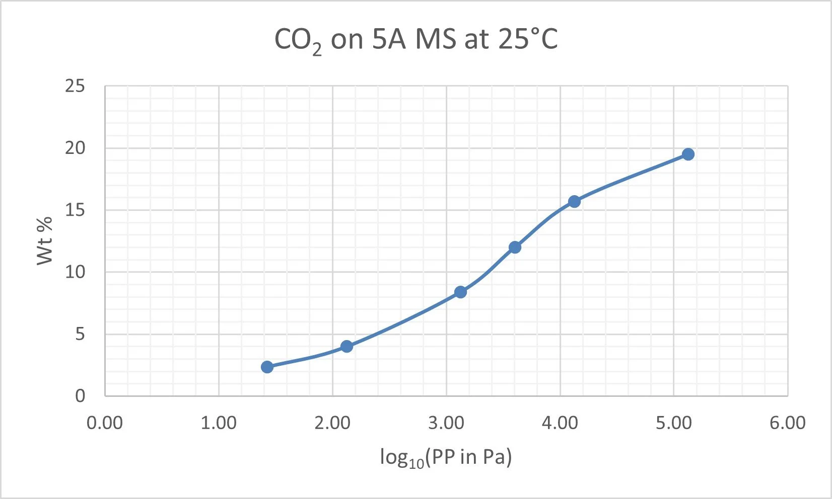
25 C Adsorption isoltherm for CO2 on 5A molecular sieve.
Sometimes two or more isotherm curves for the system are shown on the same graph to reflect the equilibrium behaviour at different temperatures.
Two or more different adsorbents are sometimes shown on a given isotherm graph to help selection of which is most suitable for a given application.
Heat of Adsorption
The isotherm graph is a convenient simplification for design purposes, but this neglects the fact that adsorption is an exothermic process i.e. it releases heat energy, and this causes the gas temperature to rise.
This may be easily understood as follows: When molecules of gas move from the energetic gas phase to a ‘calmer’ and more compact ‘state of aggregation’ on the internal surface of the adsorbent particles, some energy is released. This is analogous and related to condensation of a gas to a liquid state. The ‘heat of adsorption’ is typically of the same order of magnitude as the latent heat of condensation. The differential heat of adsorption decreases as the internal surface becomes more fully covered.
During the adsorption phase the effect of heat of adsorption is manifest in a rise in temperature across the adsorber bed. The maximum ΔT is determined by the (mass adsorbed per unit time) x (heat of adsorption)/ (total mass flowrate of gas x Specific heat). Some heat is absorbed by the bed itself so in most cases the temperature rise is a few degrees and can be catered for in the design by using an isotherm for the exit temperature.
The heat of adsorption is a significant factor in the heat required to effect regeneration of the bed.
Regeneration
Different configurations for example using 3 or 4 vessels may be used for a large facility and enables more efficient use of the energy used for regeneration. These will be described later.
The regeneration can be achieved at the same pressure as the feed, when it needs a somewhat higher regeneration gas temperature, than low pressure regeneration. This process is termed (pure) Thermal swing adsorption (TSA). The heat for regeneration may be provided by an electric heater with thyristor control or sometimes by steam. For effective removal of water from molecular sieve a temperature of 300°C is normally required. Other adsorbents such as Activated alumina require a lower temperature.
Regeneration can also be achieved by depressuring the spent bed and purging at low pressure without supplying heat. This approach is termed Pressure swing adsorption (PSA). Pressure swing adsorption uses several beds operating for short onstream periods of the order of minutes and with the various stages staggered. At least 4 beds and up to 16 have been employed on large plants.
Combined thermal -pressure swing is also often used where a low-pressure regeneration gas source is available such as waste nitrogen on Air Separation (oxygen) plants. This combination enables relatively long cycle times and efficient regeneration to ensure exit gas impurity is very low. Because CO2 is less strongly adsorbed than water, it is largely removed by depressurisation and during the initial period of bed heating. The associated heat of desorption of CO2 can lead to a regeneration gas exit temperature dropping below ambient and even frosting of the exit pipe.
Multiple Beds
Where more than one component is to be removed it is sometimes beneficial to use two (or more) adsorbent beds in series in each vessel where each adsorbent is best suited to removal of a particular species.
Examples include:
· A TSA process for both water and carbon dioxide removal from the feed to a cryogenic ASU
· A PSA process for water, CO2 and CO removal in purifying a hydrogen stream.
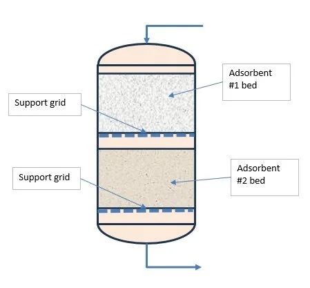
Dual bed
The beds would typically activated alumina and molecular sieve and possibly activated carbon as well.
A further situation where multiple beds have been successfully selected is for final low temperature purification of a helium stream by adsorption prior to liquefaction.
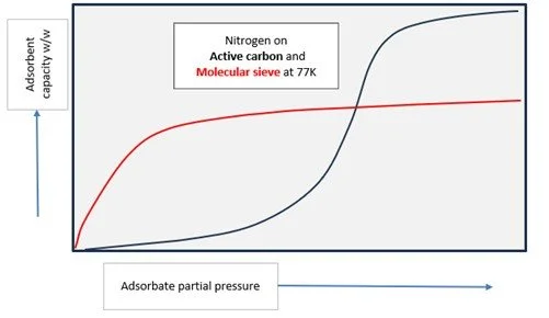
Two adsorbents with different characteristics.
Here the main adsorbate is nitrogen. Activated carbon (AC) has a very high capacity at low temperature ca 77-80K, but this capacity falls off as the residual N2 impurity in the feed gas reduces. Fortunately, although molecular sieve has a lower adsorptive capacity than AC at higher inlet N2 concentration eg 1.5-2%, it retains a good capacity even at low N2 partial pressure in the gas stream. Therefore, this second MS bed is excellent for ‘polishing’ the Helium stream to the very low impurity level (<1ppm) needed prior to liquefaction.
Configuration
A standard 2-bed system with valve arrangements is show below:

The ‘routing’ valves are shown in positions for Bed A ‘in service’ or ‘Onstream’ adsorbing impurity and Bed B is under thermal regeneration.
If regeneration is carried out at lower pressure, then additional valves would be needed one on each vessel to depressurise the ‘spent’ or loaded bed to the lower pressure before regeneration and one to repressurise a regenerated or fresh bed i.e. to equalise the pressures before it is brought on-stream.
The valve position changes would be automated by a PLC timer. The various phases in a 2-bed cycle are shown below. The relative standby, pressurising and depressurising times may be shorter than the indicative chart implies.
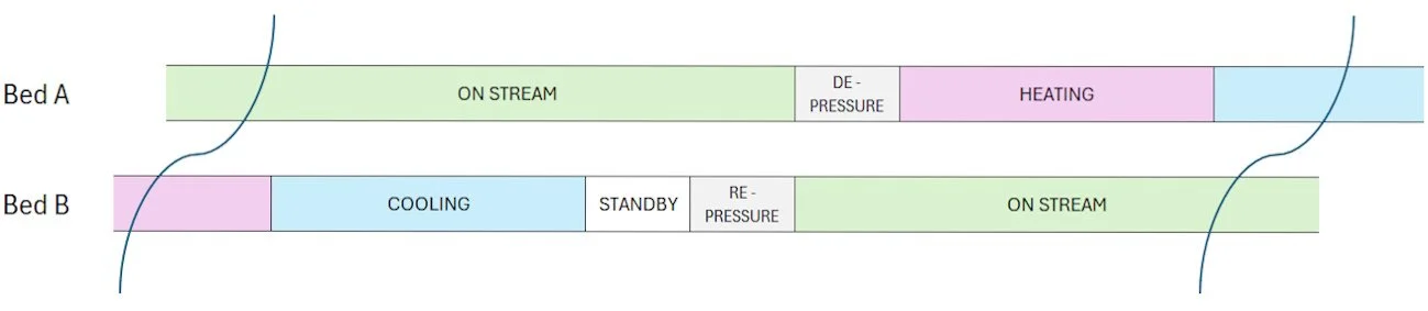
Two bed adsorber system sequence
Modelling the performance – gas and solid temperature and gas composition versus time for adsorption and regeneration phases has been tackled in many ways - from simple equilibrium models to complex CFD models.
Empirical design methods have also been developed based on operating experience of time-temperature profiles on actual plants. Typical temperature versus time profiles for a two-vessel system are shown below.
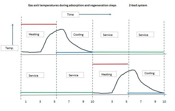
Red = regeneration heating inlet, Blue = regeneration cooling,
Green = on stream and Black = the corresponding regeneration exit temperature variation with time.
It is evident from the temperature profiles that to ensure a thorough regeneration of the entire bed, the exit temperature has to approach the inlet temperature. This leads to a significant amount of heat being ‘lost’ in the exit gas.
At the cost of additional complexity energy loss can be reduced on a large throughput plant. One such arrangement would involve 3 beds in parallel with staggered operation.
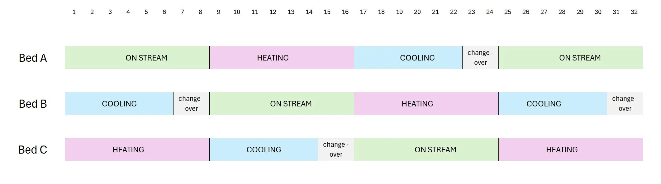
Three bed adsorber system sequence
In this arrangement the heater would be operating continuously. The regeneration gas would pass first through the cooling bed to pick up heat and then pass via the regeneration gas heater to trim the regeneration temperature and thence into the bed being heated. The arrangement can in principle recover the waste heat normally lost during the cooling phase. Also, because for each bed the heating and cooling time is double the onstream time, the regeneration flow is reduced compared to the 2-bed system. However, there are potential drawbacks with this arrangement.
Because the bed cooling shifts the hot temperature profile down the bed it actually completes the regeneration of the adsorbent. However, any residual adsorbate in the coolant gas stream will be re-adsorbed on the bed being cooled. For this reason, a detailed calculation of the regeneration is needed. Consideration should be given to the options of co-current regeneration versus the conventional counter-current with this 3-bed arrangement. An alternative way to recover exit heat would use a heat exchanger which would indirectly recover heat from the hot cooling gas exiting the bed.
Whether these more complex arrangements are worth pursuing is affected by the conflicting objectives to minimise energy use and the need for a very pure exit gas.
A similar 4-bed arrangement is possible in which at any given time, two beds are simultaneously in service in parallel but staggered by the duration of the heating period.
A drawback of the multiple vessel arrangements apart from the cost of the vessels themselves is the large number of valves. The total quantity of adsorbent hardly varies between the dual and multiple vessel systems for a given feed rate.
Pulse Regeneration.
Another relatively simple approach to reduce energy for regeneration is - termed pulse regeneration. The idea is simply to stop the heat input to the regeneration gas before the bed exit temperature has risen. At this point with counter-current regeneration flow, a significant portion of the bed is at close to the regen gas inlet temperature. Moreover, the mass transfer zone will have been thoroughly heated.
As the cooling phase starts, the pulse of heat continues to be moved through the bed continuing to desorb water. As this happens the size of the hot pulse shrinks so that at the end of the regeneration cycle there is a short temperature spike in exit gas temperature.
The optimum timing to stop the heater can be found during plant commissioning.
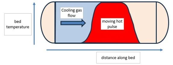
Heat pulse shrinks as it passes left to right though bed.
One factor that does affect the amount of adsorbent is the length of the on-stream period and the length of the Mass Transfer Zone (MTZ).
Mass Transfer Zone (MTZ)
As the gas stream passed through the adsorber bed its adsorbate or impurity concentration falls. A concentration wave moves down the bed. The schematic below shows the zone at the bed exit just before ‘breakthrough’.
Notes on sketch below:
1. The bed is shown horizontal although vessels are always mounted vertically.
2. The curve shows the gas phase concentration with length along (down) the bed. The equilibrium concentration of impurity adsorbed on the bed can be ‘normalised’ and follows a similar curve. The curves are not exactly coincident because a partial pressure driving force is needed for the ‘mass transfer’. I.e. movement of molecules of impurity from the gas into the into the interior channels of the adsorbent particles.
Mass transfer zone which has just reached the bed exit
The preliminary sizing of an adsorbent bed is based upon the gas flow and inlet adsorbate or impurity concentration, the adsorption time and the capacity of the adsorbent in equilibrium with the inlet feed gas. If a significant residual concentration of adsorbate remains after regeneration this must also be considered in the materials balance calculation.
In addition, a length of bed in which the concentration of impurity is reduced from the initial inlet down to the required exit is the Mass Transfer Zone (MTZ).
The length of this zone can be calculated based on a stepwise material balance and a ‘rate calculation’ if the mass transfer coefficient is known or can be calculated. Otherwise, it can be based on experience with the particular adsorbate-adsorbent system.
In general, smaller adsorbent particles provide a greater surface area per unit volume of bed and therefore give a shorter mass transfer zone, but on the other hand smaller spheres or pellets lead to a higher pressure drop through the bed.
The bed pressure drop is normally predicted using the well-known Ergun Equation or similar expressions. This has two terms, one based on laminar flow, and the other based on turbulent flow. Depending on Reynolds number and flowrate one or the other term becomes dominant.
Other practical design considerations.
The velocity through the bed is an important design parameter, as it affects the pressure drop, and the mass transfer zone length as well as attrition risk as described below.
In upward flow an excessive velocity – especially with a lower density adsorbent such as active carbon runs the risk of bed fluidisation. In high velocity downward flow, in the limit the pressure drop force can theoretically exceed the particles crushing strength for the lowest layers of particles.
If the velocity is very low, the gas may exhibit ‘fingering’ i.e. part of the flow may follow some low resistance paths eg close to the vessel wall and the resultant maldistribution can lead to early break through.
A useful initial rule of thumb is to start with an adsorption gas superficial velocity of 0.2 m/s.
During initial operation, and depending how carefully the adsorbent is loaded, some attrition can occur due to the particles shuffling as the bed settles with the gas flowing up or down. A downstream filter is needed to capture the dust released – and prevent its entry into a downstream cryogenic equipment.
Bed movement can be limited by a layer of ceramic balls on top of the bed. Successive graded layers of balls are sometimes provided beneath the bed. The support grid for the bed is frequently from ‘wedge wire screen’. This has a small opening slot at the top but then widens out in a wedge shape which prevents the screen becoming progressively blocked.
A further factor in successful bed sizing is that during the first few months of operation a progressive permanent loss in adsorptive capacity of up to 20-30% occurs after which further degradation occurs very slowly. If this degradation factor is applied the beds may not need replacing for 3-4 years or even longer.
Summary and References
This short article has tried to present a reasonable overview of the important unit operation - adsorption whilst avoiding inclusion of the details that are readily retrieved from good textbooks or, with due care from the internet.
Information on the fundamentals of adsorption and details of the relative properties of most common types of adsorbents is provided in textbooks and literature by various renowned authors and organisation including Doug Ruthven, Ralph Yang, The Gas Processors Suppliers Association (GPSA ) and its publications and conference proceedings, and Campbell’s excellent book. All the above are useful data sources.
1. Douglas M. Ruthven, Shamsuzzaman Farooq and Kent S. Knaebel, Pressure Swing Adsorption, (John Wiley & Sons Inc. 1994).
2. Ralph T. Yang, Gas Separation by Adsorption Processes,(World Scientific Publishing, reprinted 1999).
3. The Gas Processors Suppliers Association Engineering Databook (SI Edition).
4. John M. Campbell, Gas Conditioning and Processing, Volume 2, 9th Edition 2nd printing 2014.