Cryogenic Thermosiphon Reboiler
We review modelling techniques for this important equipment item used in Air Separation and other cryogenic processes. (Written by David Limb and Richard Clarke.)
Introduction
The principle of thermosiphon reboilers is well known and described elsewhere.
Briefly, a circulating boiling flow driven by static head provides an enhanced heat transfer rate compared with the pool boiling such as takes place in a kettle. This is especially beneficial for cryogenic processes such as ASU (Air Separation Unit) where close temperature differences are used to minimise entropy production (and hence power demand). In addition to the effective secondary surface area of the reboiler the circulating flow gives a high boiling film heat transfer coefficients that compensate for these small delta T’s. The heat source is typically a cryogenic fluid condensing as it flows downward in counter-current to the boiling stream.
Physical arrangements.
In cryogenic processes, the thermosiphon reboiler is normally one or more aluminium plate-fin exchanger blocks. These exchangers are often mounted in a bath or in ASU service within the base of the distillation column. The bath is operated flooded with liquid up to the to level of the exchanger top to provide maximum static driving head for the thermosiphon.
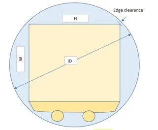
Plan view schematic of a reboiler block with twin GN2 risers
A key design or target operating parameter is the liquid recirculation rate. This is the ratio of the mass (or molar) flow of the un-boiled liquid at exchanger exit to the vapour flow. Values of 10:1 up to more than 30:1 are not uncommon. Below 6:1 there is a risk that dry patches may occur on the oxygen-rich boiling side.
To model performance of a unit with a defined geometry requires an iterative stepwise calculation of the heat transferred, and the pressure change (due to static, acceleration and friction). These both depend upon the circulating flowrate. The solution is when the circulation rate giving a total pressure loss through the exchanger equals the external static head ‘driving force’.
Internal Temperature Pinch
A consideration especially important in cryogenic thermosiphons with a close temperature difference is that the inlet liquid enters somewhat subcooled by virtue of the static head that drives the thermosiphon. Thus, a lower part of the exchanger must heat the circulating liquid up to local saturation conditions before boiling initiates. The location of initiation of boiling is determined by two factors - the heat gained and the reduction in pressure due to static head loss and friction.
Use of low frequency finning at the inlet of the boiling stream reduces the heat gained and thus widens the minimum temperature difference. Although this may reduce the frictional pressure drop, this is quite small (~10%) in the subcool zone and the nett effect is generally a wider pinch DT, which is always a design goal if the onset of boiling is to be assured.
At the warm (top) end of the reboiler the heat transfer is most intense because both boiling and condensation heat transfer coefficients are at their highest.
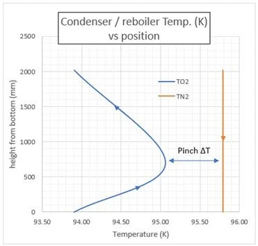
Typical temperature profiles for condensing N2 and boiling O2.
Mention should be made of the ‘downflow reboiler’ concept for which the condensing nitrogen and boiling oxygen flows are co-current downward. Although this circumvents the internal pinch, the concept adds complexity to the hydraulic design, requires a circulation pump and has potential safety concerns. It is outside the scope of the present article.
A preliminary calculation of the exchanger ‘performance’ (1.e. Duty and required ‘UA’) may be performed within a complete simulation model of the process using commercial steady state simulators such as Honeywell’s UniSim and AspenTech HYSYS. But importantly, the relationships between exchanger detailed geometry, film coefficients, pressure balance and liquid recycle are ignored.
To properly evaluate suppliers’ designs of cryogenic thermosiphon exchangers, a more rigorous performance assessment is needed which includes the above ‘ignored variables’.
The authors have therefore assessed some available ways to do this albeit with limitations :
These methods often assume there is little or no interaction between the performance of the thermosiphon heat exchanger and that of the ‘balance of the process’ in which it is located. This is generally acceptable when both boiling and condensing streams are essentially pure components like N2 and O2.
With this assumption, the detailed performance of the thermosiphon unit can in many cases be rigorously modelled in separate standalone software - either from the commercial simulation company 1) or using Excel-based software 2), 3) developed by the authors.
These are described below.
1) The standard commercial simulator software includes the capability to rigorously model a thermosiphon but only as a standalone item, which unfortunately cannot be integrated into the overall model for the process plant or a part of it.
The required ‘boundary’ stream data and properties can be extracted from the overall process model but are then fixed for the separate ‘run’ on the separate rigorous standalone thermosiphon software.
2) A stepwise calculation (with 100 steps) A reboiler modelling tool has been developed in Excel and tested by RHC. This performs a stepwise calculation (100 steps) based on the detailed geometry. It offers a choice of correlations for boiling and condensation heat transfer film coefficients and single and two-phase pressure losses, using a range of correlations, together with professional insights gained over may years. Fluid properties and thermodynamic data is generally available from sources such as NIST. Recirculation rate and design margin are determined by the model.
3) A shortcut version of this Excel-based software has also been developed by DIL/RHC in which the pressure balance and temperature pinch magnitude and location are determined. Heat transfer is based on geometry but requires input of typical average boiling and condensing film coefficients and assumes linear temperature profiles in the 2 main zones. NIST provides the required fluid properties. Recirculation rate and design margin are determined by the model.
It may be worth noting that the standard Antoine equation for vapour pressure as a function of temperature: log(P ) = A - B/(T + C) is surprisingly very accurate especially if the constants are derived to straddle the range of interest. The equation can be inverted to give saturation temperature as a function of pressure: T = B/(A - log(P)) - C.
In some situations, decoupling the rigorous thermosiphon exchanger, as a standalone calculation separate from the rest of the process model entails approximations or simplifying assumptions, which can affect confidence in fidelity of results. This potential drawback applies whether the standalone thermosiphon is commercial software or the Excel-based software tools.
The main issues /challenges:
When the boiling stream is not a pure component, the exiting recycled liquid will have a different composition from that of the liquid bath which feeds the exchanger boiling side, and both will differ from the stream fed to the thermosiphon bath.
· Some of the bath liquid (fresh feed plus recycled liquid) is withdrawn as a liquid stream, but its composition and therefore the material balance is not known a priori.
· The feed to the thermosiphon bath is often a 2-phase stream.
Described below are two ways to address this system - denoted Method A and Method B.
To illustrate the modelling approach a typical section of a process flowsheet is depicted schematically below. The process is broken down into primitive conceptual elements such as phase separator pots, mixers and splitters to illustrate these features.
In reality, there is simply a heat exchanger sitting within the bath represented here by the green bubble.
The heat source is typically a condensing stream. It is not shown explicitly but depicted as Q-in.
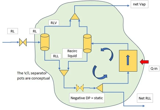
Reboiler modelling schematic showing the main streams
Method A- Using UniSim or equivalent commercial model for the overall process.
Step 1:
· The heat exchanger is defined initially as a basic heat exchanger unit.
· The feed liquid to the bath and the separation of flash vapour is modelled externally (V-100).
· The recycled liquid from the exchanger outlet is combined with the fresh feed liquid and comprises the bath composition.
· The portion of bath liquid withdrawn as nett product split off and the flow defined.
· A valve with a negative pressure drop defines the submergence head i.e DP = -(h.rho.g), where h = block length and rho = liquid density and g = gravitational acceleration.
The PSD below shows a typical UniSim model of a reboiler incorporated in the liquid recycle system, which can be used with both the methods described here.
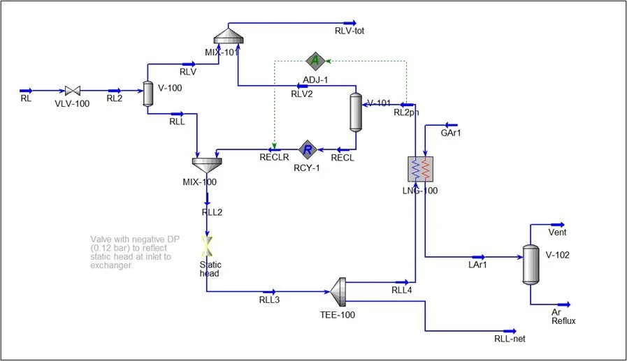
Step 2a. When the basic process model has converged, The heat exchanger is converted to a rigorous plate-fin exchanger (not a thermosiphon) by adding a full definition of geometry. (Superfluous defined exchanger parameters such as input pressure drop are removed for rigorous determination of the liquid recirculation rate – see Aadjust-1.)
· An adjust varies the estimated recycle liquid flow until the calculated exit pressure corresponds to the total block pressure drop.
· If initial results indicate the exchanger appears to be oversized a Heat Transfer Area Factor in PFE Methods section may be set at a value <1. Otherwise, the exchanger software ‘consumes’ the excess heat transfer capacity by subcooling the condensed stream leading to a cold end approach near zero.
Note: This scenario is only feasible if the condensing stream is forced to back up into the exchanger partially flooding the passages. If the condensing stream is free draining, then this phenomenon seems unlikely, and the excess heat transfer capacity would tend to ‘pull down’ the condensing stream pressure, until an equilibrium is established.
It should be noted - to avoid interaction between the Recycle operation (RCY-1)and the Adjust (ADJ-1) it appears easiest to converge these independently by alternately ‘ignoring’ one then the other until close to the solution. This requires a little time and care.
Method B
Step 1. Method B also starts with the basic UniSim process model as per Method A and depicted in the PSD.
Step 2b. When the process model has converged, with an assumed or target liquid recirculation ratio, the boiling stream inlet and outlet conditions, compositions and any necessary properties may be extracted from the UniSim model.
This data is then input to the Excel-based rigorous model(s) together with the exchanger geometry for the thermal performance and the interdependent pressure loss liquid recycle to be determined.
Note: The Excel-based calculations for a non-pure boiling stream requires phase equilibrium and property data for the boiling stream as it progresses up the thermosiphon reboiler. The approach used for a pure boiling stream based on NIST must be modified to take account of the multicomponent VLE and mixture properties.
To locate the minimum pinch requires the saturated vapour pressure (SVP) versus temperature of the liquid feeding the reboiler and also the density and specific heat or enthalpy. The SVP data can be extracted from NIST REFPROP which includes mixture data generation or from the simulation model or other Excel-based multicomponent VLE ( eg Harmens (1970) formulae for ASU components) and then fit to the Antoine relationship or other simple function over the range of interest.
The phase mixture enthalpies at a given T,P can also be obtained from the simulation model or from NIST REFPROP. (Note that liquid mixture enthalpy from pure species should be adjusted by adding the heat of mixing (H-e). This can be estimated with reasonable accuracy from the expression for H-e for regular solutions.)
Run the rigorous Excel based program (or the shortcut) to confirm that the thermal performance and the target minimum recirculation rate can be achieved.
If checking an existing design, it may be necessary to re-run the basic simulator model with corrected liquid recirculation and extract updated T,P,x and possibly update properties. However, if the calculated recirculation ratio exceeds the target (or the value assumed in the overall model), this generally means the design is conservative and further iteration may be unnecessary.
Note: In design mode the geometry can be readily modified in the Excel software until design criteria such as required stream pressures, recirculation ratio and design margin are met. The software also assesses whether the block dimensions will suit the available bath or column diameter.
SUMMARY.
Rigorous and shortcut check calculations of the performance of a vendor’s thermosiphon reboiler designs can be done using standalone software in Excel. This is straightforward for pure component reboilers such as the ASU process’s main condenser-reboiler.
The check can also be done using commercial software such as UniSim or HYSYS. However, the commercial software thermosiphon module is a free-standing module and not part of the Process simulator. The checking calculations can be done using a standard exchanger unit within the process simulator which needs features to model the effect due to recirculating liquid and static head.
For reboilers where the boiling fluid is a mixture – such as ‘rich liquid’ in an ASU, the need to consider phase equilibrium (VLE) in the boiling process adds significant complication.
The difficulty can be addressed in a number of ways. These in general have to manage the effect of the recycled liquid upon the material balance and the stream compositions and respective VLE and fluid properties. This can be tackled using the process simulator as described above, but the complex interactions need manual intervention to achieve convergence.
The other approach is to decouple the detailed reboiler modelling using the Excel-based software or the standalone commercial model, from the ‘external’ process simulation which defines the boundary conditions for the thermosiphon. This 2-step approach entails some iteration.
The iteration can be minimised if typical mixture VLE and property data is extracted from the process simulator (and NIST) and incorporated in the rigorous and shortcut Excel tools after curve fitting the extracted data over the range of interest.
Copyright DIL- RHC 01/10/2025